The Garmin Varia Mount
I returned to university after a ten-year break with a clear goal in mind: I wanted to learn how to create things from scratch. When the time came to decide on my final thesis topic, I wanted to build something I could actually use afterward — something that would remind me of my time at uni long after I'd left.
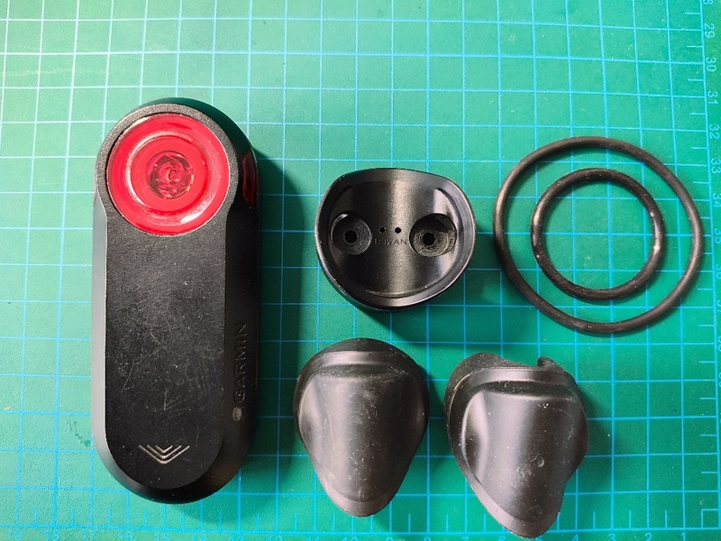
During Covid-19, I found a great escape in cycling. I had cycled before, but not on roads. The speed at which it made me forget about everything else got me hooked. One of the things I picked up was a rear radar — a device that changes the intensity and frequency of its flashing when it detects an approaching car. I'll admit I wasn't all that motivated by safety; I was just genuinely curious about how it worked.
And it worked really well, I have to say — except for one thing that was outright terrible. After a few rides, I noticed that the mount keeping the radar in place had a tendency to rotate around the seat post on bumpy roads.
Not ideal. So I thought: let's take the existing design and improve it. Instead of rubber bands, I decided to use a nylon zip tie. Yes, it's a permanent fix — you'll need a new zip tie if you want to move it to another bike — but with a 3D printer, you can churn out holders for next to nothing.
Garmin Varia RDL 515
Reverse Engineering
My plan was to reuse the existing rubber inserts and simply add a zip tie channel to a new holder body. To do that, I scanned all the rubber parts. One side of each insert is always the same, while the other is shaped to fit different seat post profiles.
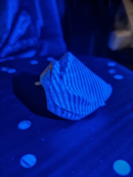
[Scanning the rubber insert with a blue light scanner]
Once a part is scanned, you end up with what's called a point cloud — no surfaces yet, but converting from points to a mesh is just a click away.
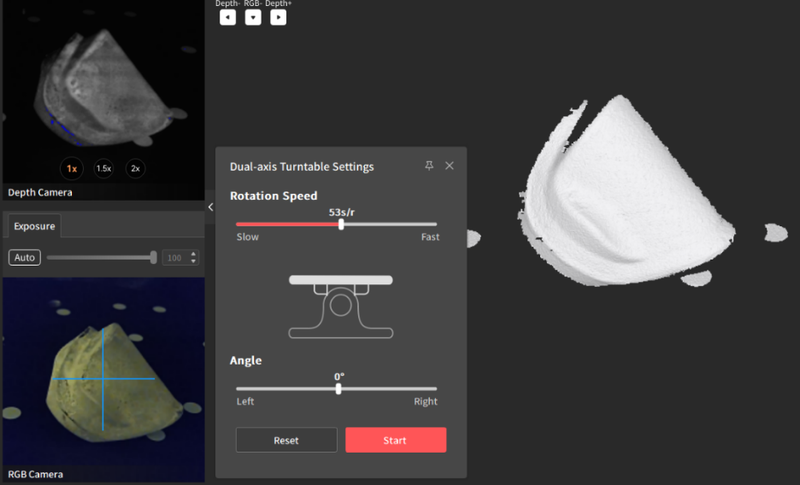
A mesh is printable on its own if the quality is good enough, and that's all you need if you just want a copy. In my case, however, I needed a proper CAD model. For the rubber inserts, auto-surfacing in Fusion 360 did the job nicely.
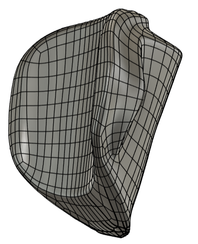
For the holder body itself, I had to start from scratch with 3D modeling. I scanned the original holder to get accurate reference dimensions, then modeled the new body with a tunnel routed through it for the zip tie.
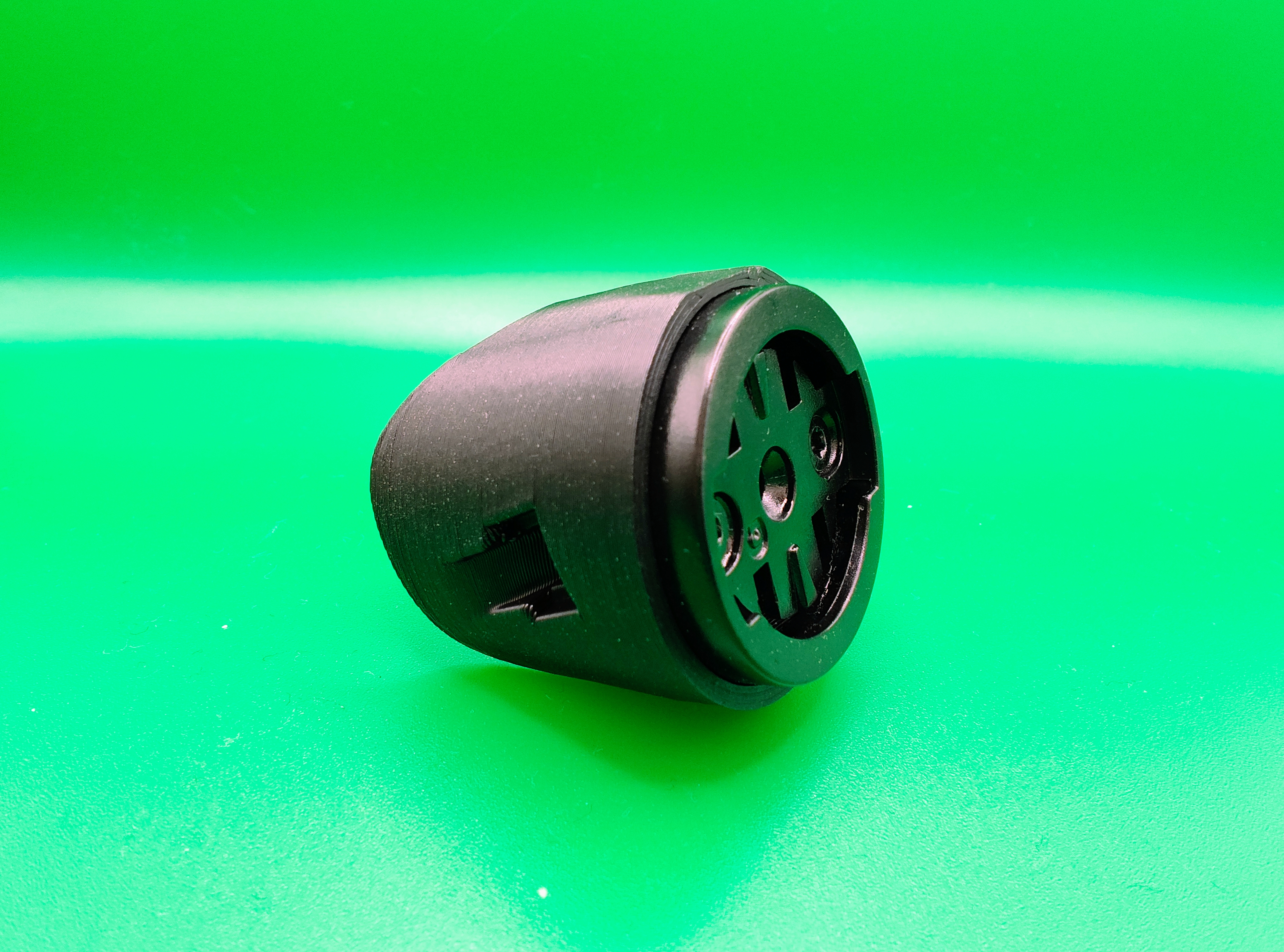
The part that took me the longest to solve was the locking mechanism. Garmin uses something that resembles a quarter-turn lock fastener, but simpler.
The locking mechanism is secured in the holder with two screws. I had two options: source an off-the-shelf locking part from a third-party supplier, or find a way to 3D print it.
You can find injection-molded versions cheaply on AliExpress (link), but that would also mean sourcing screws and inserts. In the end, I tried both approaches, and you can download both versions of the model. The real challenge was replicating the locking function without simply adding more material to make it stiffer — because tolerances matter, and if the fit is off, the radar won't twist into the locked position.
This is where I learned about the elephant foot effect. Imagine you need one part to fit inside another, but when you try to assemble them, you notice the base of one part is slightly wider than it should be.
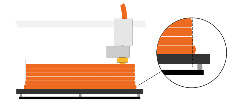
This can be caused by several factors. It's usually not a big deal, but it becomes a real headache when printing very small parts — like the Garmin lock — where a small nozzle is needed to capture fine details. Interestingly, this issue didn't appear on my first printer, a Prusa Mini, where I calibrated the Z-height manually. It did show up on the MK4 with automatic calibration. The fix was enabling adaptive elephant foot compensation in the slicer.
In general, here's what I found helps:
- Z-height calibration — the nozzle may be sitting too close to the build plate
- Build plate temperature — make sure it's within the recommended range for your material
- Using a raft — can eliminate the issue entirely
- Adaptive elephant foot compensation — available in most modern slicers
Improvements
The replaceable inserts are an elegant solution for accommodating different seat post shapes, and I understand why a rubber band makes it easier to swap the mount between bikes. But a nylon zip tie simply does a better job, and you can get a whole bag of them for almost nothing.
When a part is injection molded, it's solid throughout. With 3D printing, you have much more control over internal structure. You can set the infill — say, 20% — and the rest is air, which reduces weight without sacrificing much strength. You can also use slicer modifiers to make specific areas of the part denser where mechanical performance matters. In this case, I used 15% infill, since the part isn't under significant mechanical stress.
Results
- Weight reduction — compared to the original holder, weight varies depending on infill value; 15% infill provides sufficient structural strength and reduces weight by 35%.
- Better grip — no more rotating or adjusting mid-ride. It simply stays in place.
- Lock reliability — the injection-molded lock proved more reliable than the FFF-printed version, but I plan to try printing it in SLA using an ABS-like resin. I've been running an FFF-printed lock on one of my bikes for a year now, though I did receive some feedback that it broke during mounting — likely a combination of low temperatures and mechanical stress.